
Replacing parts on an existing reversing camera system
Do you have a reversing camera system that has a fault and requires a replacement part? This information page will help run through adaptors, and patching connections to help replace the camera, monitor, or both.
This guide is a must-read for anyone struggling to find a replacement part for their old camera system. We'll help you diagnose the problem and determine the best solution for your needs. If your monitor menu displays, but the rest of the picture is black or blue or displays a "no signal" message, the camera is likely at fault. Unfortunately, cameras can't be repaired and must be replaced entirely. If your screen is dead or unresponsive, the LCD panel is pure white or has many lines; the monitor is likely at fault. We recommend checking the power and earth connections to the vehicle electrics and remaking the power in connection before considering a replacement. If you need to attach a new camera to your existing wiring, our guide will provide a list of the necessary tools and instructions. Remember, never cut the wires to the new reversing camera, if you are unable to find a reversing camera adaptor for the wiring/connection that you have, use a patch/splice in lead to add a new reverse camera connection.
Step One - Familiarise yourself with the layout of your system
A few variations of how a reversing camera system may be laid out exist. Please see our reversing camera cable connector information page for more information to help you get your head around the general layout of the system.
The most important takeaways from the page are :
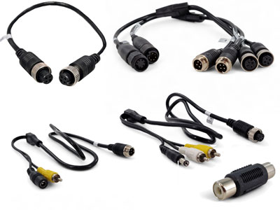
- Almost all monitors consist of a short fly lead with a connector that has between 6 to 14 pins that either pushes together or screws up and locks with a corresponding connector to a wiring loom/harness. This harness may be between 100cm and 300cm long and usually disappears behind the dashboard towards where its power supply has been fitted to the vehicle's electrics.
- The multipin connectors used in the aforementioned bullet point can be "pinned out" (wired up) in many combinations. This means that even if you find a new monitor with the same-looking connector, you will still have to remove and replace the old wiring harness. We do not recommend just plugging a new monitor in to test if it works with the old wiring unless it is a direct replacement - i.e. it is the same monitor from the SAME SUPPLIER. I emphasise the same supplier - as monitor casings can be identical between different factories - due to standard public design. It highlights the importance of buying from a reputable company like ours, who offer repairs and try to keep spares for direct replacement many years later (even helping people 15+ years after purchase).
- Almost all reverse cameras have a short fly lead, usually between 30-100cm in length, that terminates in a connector that then plugs into an extension cable. Sometimes, you may find a separate power supply; this is always the case with reversing cameras fitted with the yellow RCA Phono sockets. If you find 4 or more pins on the camera connection, the monitor is probably supplying the power.
Step Two - Check our Reversing Camera Adaptors Page
Now that you understand how your reverse camera system is laid out, i.e. you have found the actual type of connection that is present on your camera or monitor channel inputs, you should check our reversing cameras and adaptors page to see if you can find a plug-and-play adaptor set.
Step Three - Follow our replacement guide for the various scenarios below
Scenario 1 : Suspected failure of camera (most common issue)
This is the most common query we get asked about, the conversation usually starts “my screen has gone black or says no signal, I can enter the menu system and adjust a few settings but I never see a picture”.
In about 90% of cases, this indicates a problem with the camera. If your screen is functioning normally in all other aspects but fails to show an image, consider the following possibilities:
- The camera may have developed a fault, leading to a lack of signal.
- Insufficient power to the camera due to a poor connection or the monitor providing an inadequate output to the camera.
- The camera wire between the monitor and camera may have broken strands, potentially caused by cable compression or stretching.
- In rare instances, the monitor itself may have a fault preventing it from displaying the received signal.
Unfortunately, cameras typically lack repairable components and require replacement as a complete unit. Follow our guide for adding a new camera to existing wiring.
Guide to splicing in a new reversing camera to the old wiring
If you can't find an adaptor, then you will need to upgrade your connector to the more modern style used in cameras like ours.
Tools you will need:
- Multimeter
- Wire Cutter/Stripper
- Insulation Tape or Heat Shrink
- Soldering Iron/Gun
- Heat Gun (if using Heat Shrink)
- CAB041 - Splice Patch Lead to add 4 pin connector
- Reversing Camera - ensure you select the 4 pin connector when asked
Warning 1 : Never cut the wires to the new camera as this may allow atmospheric moisture to enter down the cable and wire colours may be different to advice on this page.
Warning 2 : Never cut the extension cable whilst there is power to the camera system as this may cause a short.
Method:
- Confirm that the power to the system is turned off (if the system is ignition based then keep the ignition off, if the system is incorrectly wired in to a battery/permanent supply pull the fuse.
- Cut off the old connector from the main extension wire. It may be worth cutting this several inches back from the connector as you will be adding extra length in with the CAB041.
- Ensure that the wires are separated to prevent contact with each other and anything else that electricity shouldn't touch.
- Power up the system by activating the monitor/re-plugging fuse back in
- Use a multimeter to identify the wire(s) carrying power (usually one, but occasionally more); take note of the colour (as colours may not always follow convention).
- Power down the system to proceed with making connections.
- Connect the red wire on our CAB041 cable to the identified coloured wire carrying +12V on your existing wiring (preferably using soldering).
- If your main extension cable has shielding (strands of copper wire wrapped around the outside of a wires PVC sleeving, it likely serves as the video signal cable. Connect it to the video cable on the new lead (the yellow wire).
- Twist the shielding from the old signal wire with the bare earth/shielding on the CAB041. Insulate the connections.
- Power up the system; the camera might function now, as some systems link the earth screening with the main earth in the connector. If it does not, identify the earth cable on your old wiring by touching the remaining spare wires in your old cable (ensuring none are positive) against the earth/screening on the new connection cable until a picture appears on the screen.
- For cameras with sound (if applicable), and if your monitor has a speaker, enable sound by attaching the white wire from our cable. Identify the audio-carrying wire by touching it against the spare wires on your cable until audio is heard (you may need someone to tap the camera microphone whilst you do this so that it produces a noise for you to hear).
- Organize your wiring, ensuring all wires are securely soldered and insulated.
- Congratulations! The task is complete. Now, it's time to take a break and enjoy a cup of tea or coffee.
Scenario 2 : Suspected failure of monitor
If you have checked your power/earth supply is good, unplugged the camera extension leads to check if the monitor is in short circuit protection mode, and you have checked to make sure no pins have been bent on the monitor that need re-straightening then the next step would be to replace both camera and monitor. If the original monitor was one of ours, contact us to see if we can repair the unit, or supply a replacement. If the monitor was from another supplier, regretfully we can't offer a repair, and trying to work out the pin-outs to keep the old camera can be tricky. In this case, a new camera and monitor is in order. You can use the guide below to re-use the old cable, to save time running a new wire front to back.
Guide to splicing on a new reversing camera AND monitor to the old extension cable
Tools you will need:
- Wire Cutter/Stripper
- Insulation Tape or Heat Shrink
- Soldering Iron/Gun
- Heat Gun (if using Heat Shrink)
- 1M 4 pin cable from our website to splice on to the cable (or if ordering a reversing camera kit - select the shortest length)
Warning : Never cut the wires to the new camera as this may allow atmospheric moisture to enter down the cable and wire colours may be different to advice on this page.
Warning 2 : Never cut the extension cable whilst there is power to the camera system as this may cause a short.
Method
- Ensure there is no power supply to the old system by disconnecting the positive and earth supply from the old monitor's wiring harness (if confirmed functional, these inputs may be used for the new monitor).
- Identify both ends of the extension cable, clarifying that the wire from the monitor is not the extension cable but the multiplug between the monitor and power/inputs/earth/triggers, etc. The actual extension cable is typically concealed under the dash.
- For most of our cameras, you will use only three wires inside the cable (+12V, earth, and Video). Ensure the same colours are used/matched at both ends.
- Cut off the connectors at both ends of the original extension cable (again check to make sure it is the extension cable and not the monitor or camera cable). If different colours are found, investigate the possibilities such as adaptation, a switching box, or mistakenly cutting the monitor's/camera's wiring harness. Use a multimeter and an extension piece of wire in continuity mode if different colours are confirmed on the correct cable.
- Cut the extension wire purchased from us in half, strip back the main cable sheathing, and separate the wires. Inside, find four wires: Red = +12V, Black = earth/ground, Yellow core (shielding around) = video, White = audio (usually not used). The 4-socket part will be used at the front for the camera input, and the part with 4 pins inside will be used at the rear for the camera. to plug in to.
- Start by connecting the video wire (yellow) to the screened wire of your existing wiring if available (99% of the time they do). Solder the inner core of the yellow wire on our cable to the inner core of the shielded wire on your original cable, insulating the connections with heat shrink or insulation tape. Then twist our copper braided shielding with your existing cable's shielding, and solder these together to prevent separation and maintain protection from interference to the cable.
- Attach our red wire to a cable of your choice, ensuring it is replicated at both ends. For instance, if you attached our red wire to a pink wire with a yellow tracer wire at the front end side on your old cable, also match our red wire to the pink/yellow tracer wire at the rear end side of your old cable. Solder and insulate.
- Connect the black wire of our cable to a colour of your choice, ensuring consistency front and back (As mentioned in the point above. Solder and insulate.
- If the new camera has a microphone and the monitor has a speaker, attach the audio wire on our cable (white) to a cable of your choice. Solder and insulate.
- At this stage, you've essentially transformed your old cable into one of our 4-pin cables, and the installation will now follow the standard instructions provided in your system's manual.