
Reversing Camera Cable Information
You will find that there are often lots of different types of cable and connectors involved in a reversing camera system. This guide is written to help you navigate and understand the types of cable you may find.
Monitor Cables (Monitor Wiring Harness / Wiring Loom)
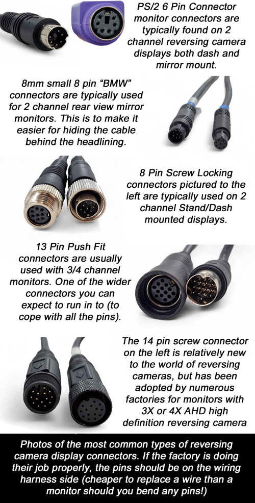
Starting at the front end, you will find a short length of cable attached to the monitor. This is usually referred to as the fly lead or disconnect point. The connector at the end of this fly lead will usually have between 6 and 13 pins/sockets inside it. If your monitor only supports two channels we tend to see between six to eight pins, if your monitor supports three or more we tend to see the 13 pin versions.
The connector will plug in to a wiring harness/loom that will take the power, earth, and trigger wires (reverse/indicator light) and channel inputs up the one wire to the monitor. At the other end of this cable, which is usually hidden towards the dashboard area, you will find where it splits out in to these inputs. Most of the time the split is done at a moulded piece in the wire, although on some factory fit systems you may find a small box where this occurs. Systems older than 15 years often use a box that did the same thing, in fact we used to have this layout when we first started out.
This wiring harness is usually somewhere between one to three metres in length. It isn't often any longer than this because as you can imagine you have to keep the wire thickness down to fit so many different wires inside the cable. A thin wire due to its resistance cannot be very long before you start encountering issues with signal loss.
One of the most common questions is my monitor has gone can I buy a new monitor to plug on to my existing cabling. If your old monitor was supplied by us, this usually isn't a problem. If it was supplied by somebody else chances are it wouldn't be this simple (although we do stock adaptors for Sargent Electricals factory fit systems fitted to a lot of Swift/Autotrail/Bessacarr motorhomes, which would be a simple swap). This doesn't necessarily mean that you can't replace just a monitor, it just means a bit more investigation work is needed before doing so.
If you do need to replace the monitor and wiring harness, your first job will be to trace where this wiring harness leads to and establish what type of connexion you have going into the channel inputs. Fingers crossed it will be a universal type that will have established pin out conventions. The two universal types are phono RCA connectors and 4 Pin aviation screw connectors (see further down in extension cables section for pictures of both types). If you find one of these two types you would simply need to go to our monitors category and select the monitor of your preference with the correct/ corresponding connector type. You would then need to remove the old monitor cabling and replace it with the new wiring loom that comes with all of our monitors. Moving the old camera connectors and power connections from the old wiring harness to the new one.
Below is a photo of one of our 3 channel dash/stand mount monitors wiring harness. Other monitors may have slightly different appearance, however they follow the same general layout ie a connector to plug in to the monitor on one side, and the basics (camera inputs, trigger wire(s), power, earth wires). On most of our monitors we have a 2.1mm DC power socket installed that will allow either our standard red/black hard wire cable (supplied) to fit, or one of our optional lighter plug/fuse tap fittings.
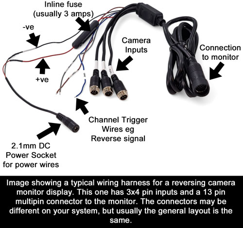
We mentioned trigger wires, this is simply a wire that is present on the wiring harness that tells the monitor when you are in reverse. Typically this will turn the monitor on (if it was off), and select the related channel that is linked to the trigger wire. On two channel monitors you will typically only have one trigger wire, this is usually linked to channel 2/V2.
In the photo above you will note that there are 3 coloured wires, these state which channel input number they are connected to. So for instance you have connected a left hand side camera to channel 3, and you want this to come on full screen when you indicate left, you would need to attach the trigger wire labelled channel 3 to the left indicator (you would also need to set a delay time on the monitor settings to stop the screen flashing on/off with the indicator flashes).
Extension Cable (Main cable that runs between monitor and reversing camera)
The longest cable you will find runs between The monitor / display and the reversing camera at the rear. This is known as a reverse camera extension cable. We mentioned that there are two that are considered a universal type because they have established pinouts ie they are usually wired the same and interchangeable between various factories.
I will break this section down into the various connector types you may run into below.
4 Pin Aviation / 4 Pin Screw Connector / GX12 Connector Cables
This is our favourite type of connector cable, and it is one that we have used from when we first started trading in the mid 2000s. It is a waterproof connector that has been designed to carry both power to the camera, as well as signals from the reversing camera. If your camera has a microphone it even carries audio signal, as well as the video feed.
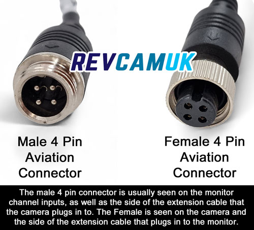
The term aviation connector often confuses people, they say the camera isn't on an aeroplane! Originally this type of connection was established in the military aviation sector. It is a tried and tested good quality connector to use. We have a lot of farmers in the north of Scotland that use this on exposed connections in all weathers without issue.
We mentioned earlier that this type of connector has a common pin out arrangement. This is true in 99% plus of all cases, however we have seen a couple of manufacturers that decided to go against the norm (luckily in these cases they also put the male connector where the female should be and vice versa).
The pin outs below are for the 99%+ of 4 pin connector reversing camera systems out there in the market. If you have a 24V vehicle you may be confused with the pin marked 12V, this is because 4 pin based systems almost always have a dropper built in to the vehicle monitor that drops the voltage down to a regulated +12V feed for the reversing camera.
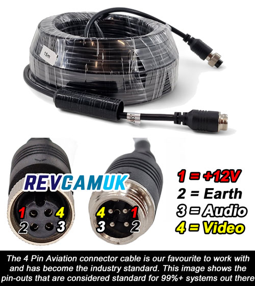
Some factories may differ cable colours, but as you will see in the photo above, the yellow wire in our cables carries the video signal and connects to pin 4 in the waterproof moulded connector. The copper braiding wrapped around this yellow wire is known as shielding, and also acts as the video earth. Shielding helps to prevent any unwanted interference from affecting the video signal.
The red wire inside the cable carries the +12V power supply for the reversing camera, whilst the black wire carries the earth/ground wire. As mentioned earlier, the 4 pin systems usually carry 12V even when placed on a 24V system, this is because all the 4 pin monitors we supply and have seen from others have droppers built in to send a stabilised 12V supply to the camera. One word of caution if you have a 24V lorry, it may be worth double checking this pin with a multimeter as there is a rare possibility that someone has just added a 4 pin adaptor and provided a separate 24V supply to this, or the monitor used to have a power regulator box that someone has cut off (rarely happens but I have heard of both of these being found in the past).
The wire connected to pin 3 in the moulded 4 pin connector is the audio wire. On our cables it is white in colour, but we have seen other instances where it has been green/blue. Not that many reversing canvas actually have a microphone, so most of the time this wire doesn't actually get used.
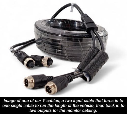
Usually most of the four pin aviation cables you will find will be single channel, but if you have a twin camera system especially one supplied by us you may find a twin channel 4 pin aviation cable. These twin signal cables we label as Y cables because both ends make the Y shape as it converts from a single cable into two. See image below of this type of cable arrangement.
RCA / Phono / Composite Video connector Cables
The RCA phono connector cable is probably a type that you've seen elsewhere in your life it was and still is a popular method for connecting video signal to devices like TV. The phono cable is a very simple coax cable ie has an inner core wire for the video signal with a PVC flex covering, plus an earthed shielding wrapped around the outside for the video to prevent interference affecting this inner signal wire.
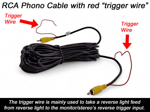
There are phono RCA cables that have a small red wire coming out next to the connector on each end (see photo below). We stock these in fact, this small red wire is actually designed as a tool to bring a reverse trigger wire to the front of the vehicle. Although we have seen these wires used to send an ignition based power source from the front of the vehicle to the reverse camera power wire.
The phono RCA connector cable used to be one of the most common methods of connection for reversing camera kits. But eventually the benefits of the monitor providing a regulated 12 volt power feedback to the camera avoiding CANBUS issues meant it became less popular, except when connecting to a stereo head unit eg Sony, Pioneer, Kenwood.
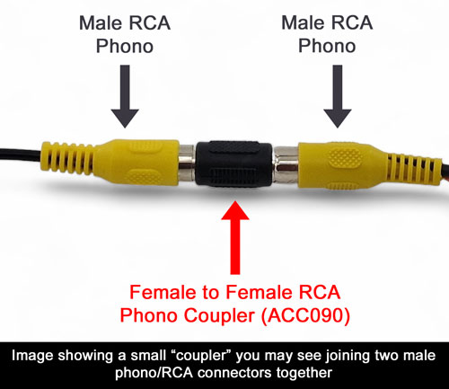
Occasionally you may find a connector piece joining two of the RCA Phono cables together. See image of what this looks like below.
DC Power Extension Cables (Sometimes run alongside RCA/Phono cables)
Because the traditional phono RCA cable doesn't take power to the reversing camera, occasionally you will find people have run a power extension alongside this cable. It could be a simple red/black twin wire, or it could be a DC extension type of cable. Usually reversing cameras use size 2.1mm/5.5mm connectors so this tends to be the type of DC extension we tend to see.
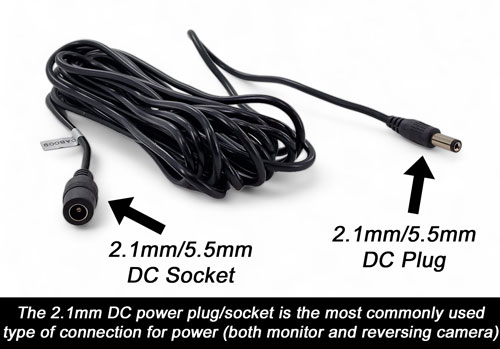
On this type of connector the power is always sent down the centre pin, whilst the surface on the outside of the DC plug is the earth/ground.
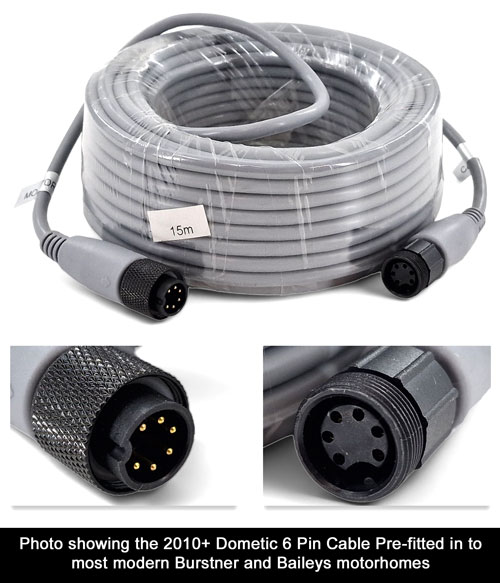
Dometic / Waeco 6 Pin Screw Connector Cable
We see this type of cable come as standard on most modern Baileys and Burstner motorhomes. We also see it on other motorhome brands where a Dometic/Waeco reversing camera kit was installed as an aftermarket addon. The cable will be light grey in colour, and will usually have a silver label saying "Monitor" at the front end, and "Camera" at the rear end. The picture below shows the cable and it's connectors.
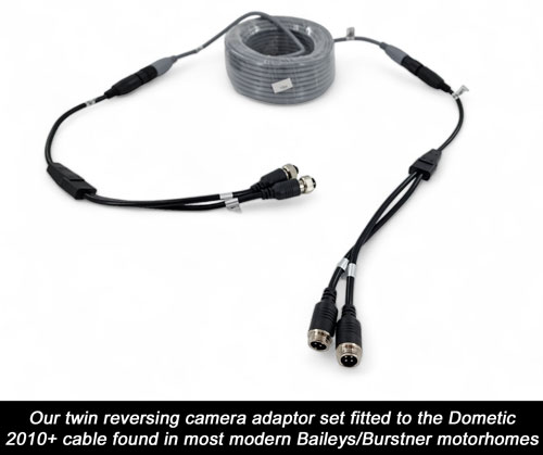
We sell adapters so that you can utilise this 6 pin cable for your new reversing camera system. We sell the adapters in pairs front and rear since when we were getting the adapters made up we discovered three different ways to how they had been wired up inside. We always advise people that when replacing a Waeco / Dometic reverse camera there is a possibility that you will also have to replace the monitor with one of ours too. We can supply both single channel Dometic/Waeco compatible reverse camera adaptor cables and twin channel Dometic/Waeco compatible reverse/rear view camera adaptor cables (the cable can support two channels and this last cable splits to two 4 pin aviation connectors on both sides) - see photo below.
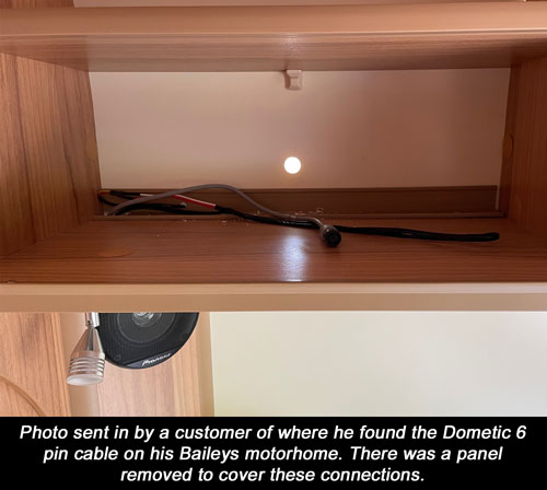
The photo below shows one of the common locations that the rear of your cable will end up in your motorhome. The photo was sent in to us by a customer with a Bailey motorhome.
The video below shows our twin cable adaptors being installed on to my fathers Burstner motorhome using the same pre-fitted cable. The video shows where we found the two sides of the connectors.
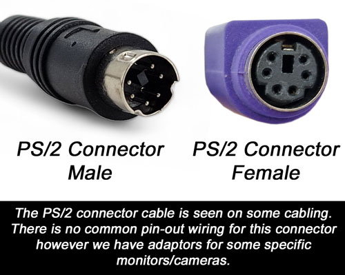
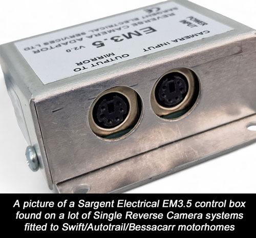
PS/2 Connector Cable (Commonly seen on Swift/Autotrail/Bessacarr motorhomes supplied by Sargent Electrical)
The humble PS/2 connector was originally developed by IBM for their Personal System/2 series of personal computers. You may recognise it from computer mice/keyboards before USB took over as the most common type.
We have seen this connector on monitors, extension cables, and reversing cameras. Obviously because the connector wasn't designed for this purpose, there will be lots of different ways that this wire has been wired up inside. If you have a Swift/Autotrail/Bessacarr motorhome with this type of connection (original supplier Sargent Electrical) then you are in luck, as we have a range of PS/2 Reverse Camera adaptors to support you should something fail.
If you have this type of reversing camera system you will likely have a control box installed that connects into the monitor display. This is usually an EM 1.0 box, EM 3.5 box EM 5.0 box or EM 5.6 box. The EM5 series boxes are almost identical with minimal change and are found on the factory twin camera systems. See the most commonly installed single camera EM3.5 box below. The EM1 and EM3.5 box use the same pin-outs for the reversing camera. The EM5.0 and EM5.6 twin camera box uses the same pin-outs as each other (it is worth mentioning that channel 1 and channel 2 inputs have different pin-outs to each other). We developed adaptors for both.
The photo below shows the PS/2 female connections panel mounted on a Swift motorhomes EM3.5 control box, one for the camera input, one for the monitor output (both pinned out differently - we have adaptors for both).
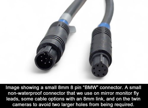
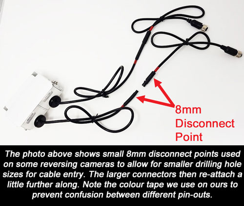
8 Pin 8mm diameter "BMW" connector cables
You may find a small push fit connector that houses 8 pins and is roughly 8 millimetres in diameter, this is known in the industry as a BMW connector (although we have never found a link to BMW ourselves). We use it on our mirror monitors for the disconnect point, as it makes it easier to feed the connector behind the headlining. We also use it on the front of some of our extension cables to aid with feeding through tight spots, plus some models of reversing camera eg twin lens again to aid with feeding the cable through with minimal size requirement.
We have seen a couple of suppliers in the UK use this as their main connector (Vision UK and Vision Plus). Although we do like to use this connector type on cables that are internal, We would not recommend this connector if it was to be stored outside. This is because it is not fully waterproof, and it can also be affected by freeze/thaw action during winter time. We have seen this type of connector break apart in winter when used externally.
There are no standard pinouts for this type of connector, in fact we have around a dozen variations of how our a pin connectors have been pinned out. Luckily, we had the foresight to colour tape all of our 8 pin 8 mm disconnect points so we can always ensure the correct ends are fitted together eg red to red, or blue to blue (notice that the picture below has blue tape). If you do have a camera fail from one of the two companies we mentioned earlier (Vision UK / Vision Plus) then we do have an adaptor to allow one of our cameras to act as a replacement.
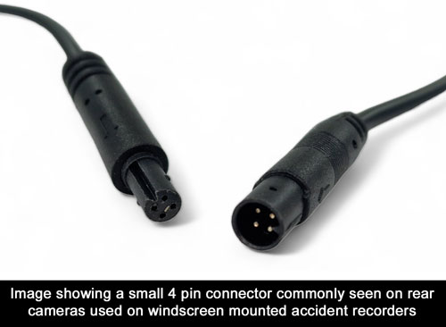
4 Pin Small connector cables (usually accident recorder rear cameras)
With the increasing popularity of a rear facing camera plugging into a windscreen based accident recorder we have seen the addition of these small four pin connector cables. The problem again is that there are no standardised pinouts for these.
We actually use these four pin small connectors as a disconnect point on some of our small number plate reversing cameras eg our number plate bolt camera - where a small plug is necessary to get through tight gaps. Ours (and many other suppliers) do convert back in slightly further down the cable into conventional universal plugs eg RCA phono connectors or 4 pin aviation connectors. If you find a small 4 pin connector on your system we advise looking a bit further along to see if it changes to a universal type that will be easier to work with. If your monitor is a small accident recorder, then there is a chance that this small 4 pin cable is your main cable with no other conversion points.
We have seen extension cables for sale for these small 4PIN cables, but due to the variance we have seen in pinouts we have chosen not to have one produced since we would not know where to put the screened video signal cable. Again same with the 8 pin version previously discussed, this plug arrangement is best suited to be mounted internally.
Reversing Camera Fly Leads
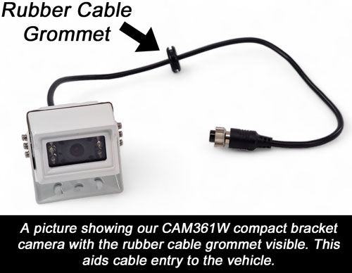
On almost all reversing cameras there will be a fly lead that then attaches to the main extension cable. This fly lead is very often going to be inside the vehicle and usually there will be a cable grommet and sealant where the cable enters through the back of the vehicle. This means that when you change your reversing camera, or wish to check what type of connector is fitted, you will have to remove this sealant to gain access to the connector (unless the connector is visible in a rear cupboard panel - as shown in an earlier photo). We usually see lengths of between 30cm and 100cm until you get to the connector.
The type of connector you find usually matches the type that is on your wiring harness for the monitor and your extension cables. We often get people phone up saying they have a small white bar jumper style connector, we immediately know that they have opened up the reversing camera itself and are looking at the myriad of internal connectors to go from different printed circuit boards inside the camera. You will never be able to change the camera at this point, even if you had the exact same model we would not recommend it. This is because the camera would need rebuilding in a cool dry airstream, as the factory does to ensure the lowest humidity air remains inside the camera to avoid any fogging/misting issues during operation.
As mentioned earlier some of our reversing cameras eg the twin lens camera have got two parts to them ie a small disconnect point, then the larger 4 pin aviation connector.
Another thing to mention when it comes to the fly leads, is that on smaller cameras there are occasionally a small moulding piece that houses a voltage dropper. A voltage dropper is common on reversing cameras to reduce the supply to the printed circuit boards from 12V to around 3-5V. On smaller cameras this has been placed on the cable to keep temperatures inside the camera down. You don't normally see these mounted on the cable on larger cameras since the heat can dissipate a lot easier. Very often this small piece is not waterproof and has small holes in to help lose the heat that occurs during the voltage step down. We would also recommend not covering this with waterproofing tape because doing so could allow heat to build up and prevent it from working properly.
We hope you find this information useful. If you have another type of connection that you cannot see on this page please feel free to contact us. We may have some advice, or if the demand is likely to be high we may be able to have some adapters made up to assist people in the future.